Dismantling ARToolkit Part 3: Locating Vertices
My previous post detailed how the contour of a marker is identified. I now continue my quest, using this information, to extract the locations of the corners from the image.
Estimating Vertex Location
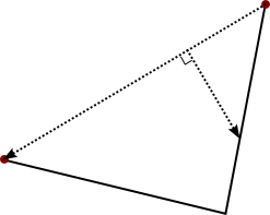
The first stage is estimating the location of the vertices. We already have an estimate of one corner — the first point in the contour chain. Finding the next one is also relatively simple. Starting at the first point in the chain (i.e. the first vertex), identify the point in the chain that is the furthest from it. This is just an application of Pythagoras’ theorem. Two situations can arise from this, assuming the blob in question is actually a marker:
- an approximation of the opposite corner has been found, or
- one of the corners directly connected to the starting point has been found.
Examples of these can be seen below.

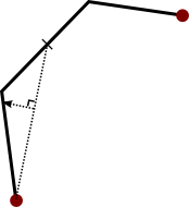
Now things get a little more interesting. To find the two remaining corners, two different approaches are required, both of which are similar. The aim is to maximise the length of a line ln which is perpendicular to the line lse through the start and end point for each chain segment. For each point between the start and end index of the chain segment, the length of ln from said point to its intersection with the line lse is calculated. It is this length that needs maximising. Diagrams always make things clearer:
For each point in the pixel chain between the start and the end index, the length of ln is calculated and information about the point which has the current maximum length is recorded. If some function f(x) of the greatest ln exceeds some threshold, the associated point is considered a vertex or corner. In ARToolkit, f(x) seems to be defined as the number of pixels in the blob divided by 75. One assumes that 75 is an effective magic number.
In the first situation described above, where the second vertex (V2) identified is the the one opposite the starting vertex (V1), this method is applied to the points in the chain from V1 to V2, then from V2 to V1 at the end of the chain. If, however, the second situation is occurring, an estimated intermediate point is identified on the side with two vertices to find. This is as simple as the point whose index is numerically half way between the current start and end index. This intermediate point is then used as an index for the vertex finding method.
If you’re reading this from an implementation point of view, then you’re probably wandering how you know which situation is happening. The answer is: you don’t.
In ARToolkit, a limited recursive method is used to find the furthest perpendicular point. If the distance is above the threshold then the method is applied again between the start point and the identified point, and then between the identified point and the end point. In ARToolkit, this method is known as get_vertex(…) and can be found in arDetectMarker2.c.
One of the outputs of this recursive function is the number of vertices it finds. So, for the first situation above, the calls for each half of the chain would both find one vertex. For the second situation, one of the sides would return zero and the other would return two. If this happens, the side with (possibly) two vertices is split (as above) and the method is run again, hoping for one vertex from each call. If more than four vertices are found it’s not a quadrilateral. This is all the information needed to implement what’s discussed above.
Refining Vertex Location
We now have an estimation of where the vertices are. In practise, these estimates may be quite bad when it comes to recovering the contents of the marker — we need to improve them. Currently, we are constrained by having to use an element of the pixel chain for the marker as the vertex’s position. Let’s get rid of this constraint.
Basing the location on one pixel is not very accurate. Consider the situation where there is a dark object in the background behind the marker which makes it look like the vertex is further from the centre than it actually is. We can use the rest of the pixels on each side to significantly improve our estimate.
Performing some kind of linear regression on the points on each side will produce a line of best fit through the points. The intersections of these lines can then be used as the location of the vertices with a fairly high level of confidence. ARToolkit uses a technique known as Principal Component Analysis (PCA for short) to perform this regression. The following image shows the output of a test program I’m currently writing, after the estimates have been improved:
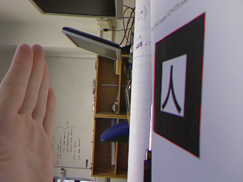
Note that the red pixels are those in the contour chain for the marker, and the green-blue crosses show the refined extracted vertices.
Consider this image a teaser for my next blog post. To avoid an excessively long post, I’ll give an overview of how PCA has been employed next time.